Altium Plated Slots
Plated and Non-Plated Slots and Cutouts
About this tutorial
This tutorial shows you the capabilities and what you need to do to achieve elongated holes, plated and non-plated slots and cutouts.
- I’ve been working recently on a new top secret project that used multiple slots in the board. Normally I just define them as slotted pads in Altium and the board house deals with it. Standard slot as a pad Usually I just add a pad that’s defined as a slot with a very small pad in the middle.
- Best Practices for Plated Slots We see a lot of different footprints and component types for PCB Assembly at Bittele Electronics. A majority of through-hole part footprints are designed with circular holes to accommodate circular or square leads.
- The slots are done in a different step than the via drilling. $ endgroup $ – Some Hardware Guy Dec 14 '12 at 3:13 $ begingroup $ Humm ok.I just feel unconfortable with so many different ways to interpret a PCB and repesent a slot.and OSH Park dont show them, unless you put it on the board edge layer I think $ endgroup $ – mFeinstein.
The battery terminal tabs should come up through slots in the PCB, and solder to a pad around the slot perimeter. I created a new connector in our parts library as a through-hole with the dimensions of the slot I need. The three choices for hole types are 'round', 'rectangle', and 'slot'. Generate separate NC Drill files for plated & non-plated holes - check this option to create separate drill files for plated and unplated holes. Use drilled slot command (G85) - check this option to use multiple drilled holes to create slots.
tldr;
- For Plated Slots a maximum length of 15.0mm (5/8 Inch) and tool diameter of 0.7mm (0.027in) to 2.5mm (0.098in)
- Non-Plated Slots have the same parameters as plated slots, except when they exceed the maximum length, then make sure they can be milled
- For Inner Millings, i.e. cutouts, use at least 1.8mm (0,07in) diameter and always confirm with our Board Viewer

Plated Slots
We support plated slots with a length of up to 15.0mm (5/8 Inch) and a width (or tool diameter) of 0.7mm (0.027in) to 2.8mm (0.11in).
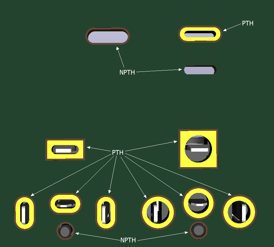
Typical use case of plated slots.
As we give a gurantee on our renderings you should always use the Board Viewer to check if plated slots are detected properly. Use the 'Highlight Drills' Button for this.
Enable drill highlight
This plated slot will be manufactured properly, shown by the orange color.

Eagle Users should always check if a slot was detected as plated or non-plated slot.
Non-Plated Slots
Non-Plated slots have the same minimum size as plated slots of 0.7mm (0.027in) and maximum length of 15.0mm (5/8 Inch). Please note, if the slot is longer it may be milled but in this case its diameter must be above 1.8mm (0,07in). Use the Board Viewer to check how your slot will be manufactured.
'Milling Path' used to display milling of non-plated slot. In this case on a Raspberry Pi Hat.

Non-Plated slot highlighted in blue color.
Same slot as shown above.
Cutouts
Cutouts will always be milled and may have any shape you like. A milling tool with 1.8mm (0,07in) will be used, because of this all cutouts need to have at least this size.
Cutout with milling path highlighted.
I’ve been working recently on a new top secret project that used multiple slots in the board. Normally I just define them as slotted pads in Altium and the board house deals with it.

Usually I just add a pad that’s defined as a slot with a very small pad in the middle
This time I was using OSH Park, and as it turned out things were not that easy. Their process does not support milled slots in the drill file. Instead slot outlines need to be on the board outline layer, and at least 100 mills wide. After a bit of fiddling, here is how I got there (This assumes you have the part footprint open for editing in PCB Library editor) :
- Draw a closed outline of the slot on the keepout layer, making sure it’s 100mil or wider. This also helps making sure polygon pours stay away.
- Go to Tools> Convert>Create Region from Selected Primitives
- Click on the newly created region and check “Board Cutout” box
Making region a board cutout
- Add “CUTOUT” text inside the cutout on the keepout layer
- Update your parts from the library or place your new parts
- Do placement/routing/design rule checks
- When generating Gerbers, go under Gerber Setup>Layers and make sure to check Plot box near Keep-Out-Layer GKO. This will be your board outline/slots drawing for Oshpark
- Check Gerbers and confirm that GKO layer now contains outlines for the slots:
Section of Keepout layer showing board outline, slots and the text for the fab
- Submit files as usually
Altium Plated Slots Coins
Big Disclaimer(s)- I am yet to receive my boards back, so while it appears everything satisfies the specs, I may be completely wrong and the boards will be ruined. I’ll post an update once they come in. The directions are for Altium 13, so if you use 14, some menus may look different. My keepout layer contains board outline as I generate that from board shape by default.